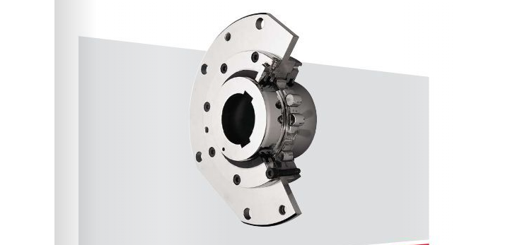
BARREL COUPLINGS FOR CRANES
The barrel coupling is basically made up by a sleeve-flange with semicircular internal teeth, a hub having external teeth with the same shape and a series of hardened steel rollers which are housed between both parts. The internal transmission area is made tight by mounting a cover at each side with their corresponding retainers, preventing, in this way, any foreign substances from getting in as well as preventing the lubricant from leaking. Two retainer rings mounted on the hub, one at each side of the teeth, limit the axial displacement of the barrel rollers inside their housing. To this regard there are 2 different constructive models. Basic models, named as NT..., in which retainer rings are directly in contact with the barrels and new generation models, named NTSG..., in which extra thrust rings are installed in between the barrels and retainer rings.
The Torque is transmitted to the receiving flange of the drum, usually, through two diametrically opposed flat carrier faces which can be found at the periphery of the coupling flange. The friction effect of the attachment screws of both flanges also takes part in this transmission. Other systems, as adjusted bolts or similar, can also be used preparing the flanges accordingly.
we can supply barrel coupling with size 2.5 MM to 620 MM
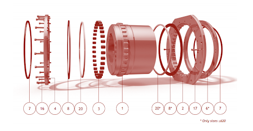
- Hub
- Sleeve-flange
- Barrel
- External cover
- Pointer
- Internal cover
- Joint
- Retainer ring
- Carrier face
- Wear control marks
- Axial adjustment mark
- Pair numbers and assembly points
- Lubricant filler
- Lubricant overflow hole
- Flange pulling hole
- External fixing screw
- Internal fixing screw
- Hub pulling hole
- Cover pulling hole
- Thrust ring (only for models NTSG...)
- Lubricant adaptor (only on request)